Progress on Project
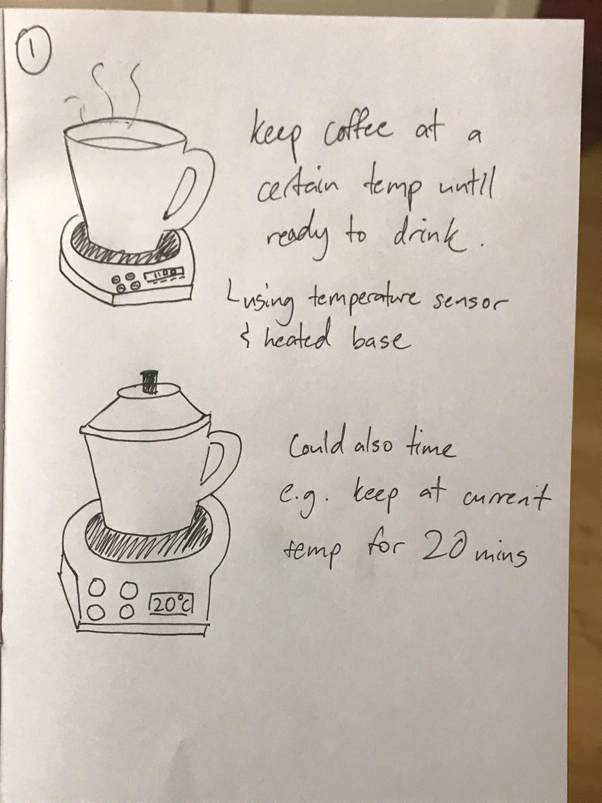
Here are some ideas I have in mind for now for my project:- -Timed Coffee Warmer
(base will heat up & can be controlled or turned off with control panel)
keep drink at a certain temperature until user is ready to drink
How Arduino can be incorporated: Temperature sensor required to regulate the temperature of the drink and heat up the base.
Pain point/reason for product: Parents drink coffee every day and sometimes it gets cold because they are distracted and wait too long.
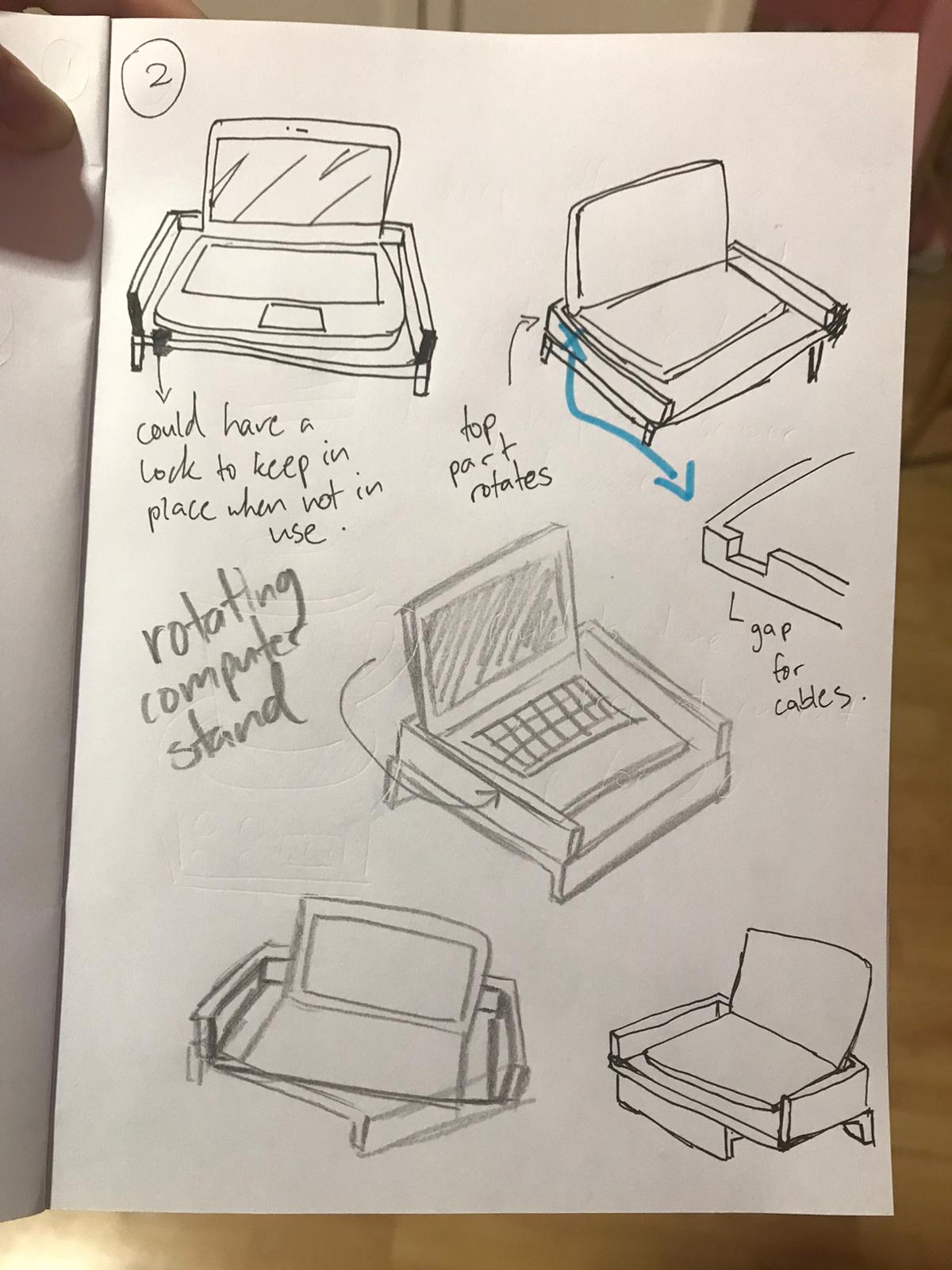
- Rotating Computer Stand
Computer stand that can rotate and be locked into place (when facing forward). Additional: can reset to face forward with the push of a button.
How Arduino can be incorporated: top part can rotate back (reset to front) with the push of a button.
Pain point/reason for product: Due to the length of my Macbook charger cable and placement of the power socket, I use my computer to charge my phone. Sometimes I will pull on the cable to use my phone while sitting on my bed which causes the computer to rotate on its makeshift stand. If I am careless and pull too hard, the computer falls onto the table.
Decision for Project
Mr Dorville provided a list of sample projects we could use and modify and I was interested in the PlexiCLock, Timelapse Motor and Volume Control Knob in particular. I decided to choose the volume control knob as it was my favorite and simpler compared to the other two. The components are also easier to obtain.
Some variations of the volume control:
- Oversized Volume Control Knob
- Vintage Rotary Phone Dial Themed Volume Control (they used a real phone dial as part of the design)
- Modern Design
Project Name: Sound Control Knob
I have decided to make a combination of the volume knob that Mr Dorville found (as it includes steps for the user to have a sense of the scale, allows you to skip and pause songs by clicking), and the modern version's design, with a sleek look.
Bill of Materials Draft
- 1 x Rotary encoder (check), using b10k rotary potentiometer.
- 1 x Arduino Pro Micro/Arduino Leonardo (check?), using Arduino Uno.
Initial Sketch
Outer Casing: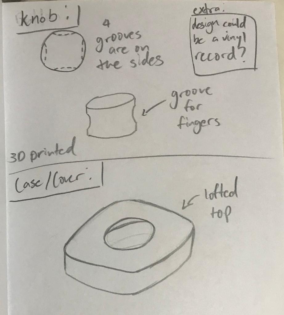
Instead of doing a knurl surface on the side of the knob, I will make grooves for the fingers on the sides for ergonomics.
Developed Version:
After consulting my lecturer, here are the improvements and changes made:
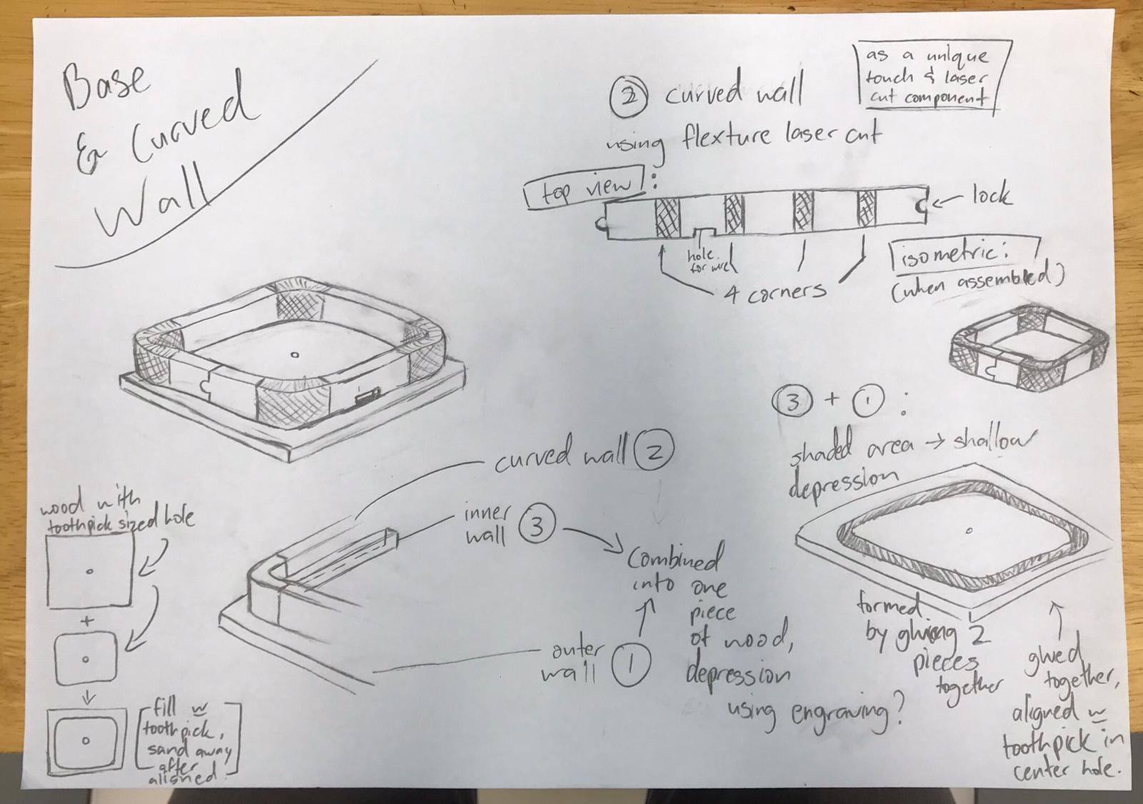
The case will be made using laser cutting, with the "flexture laser cut box" method that allows a flat piece to be bent into a curved wall.
There are many designs and patterns for the flexible hinge. This adds to the aesthetic and checks the requirement of including a laser cut component in my project.
The lid and base will also be made using laser cutting. I have also added some spaces for the wires and components.
New Sketch:
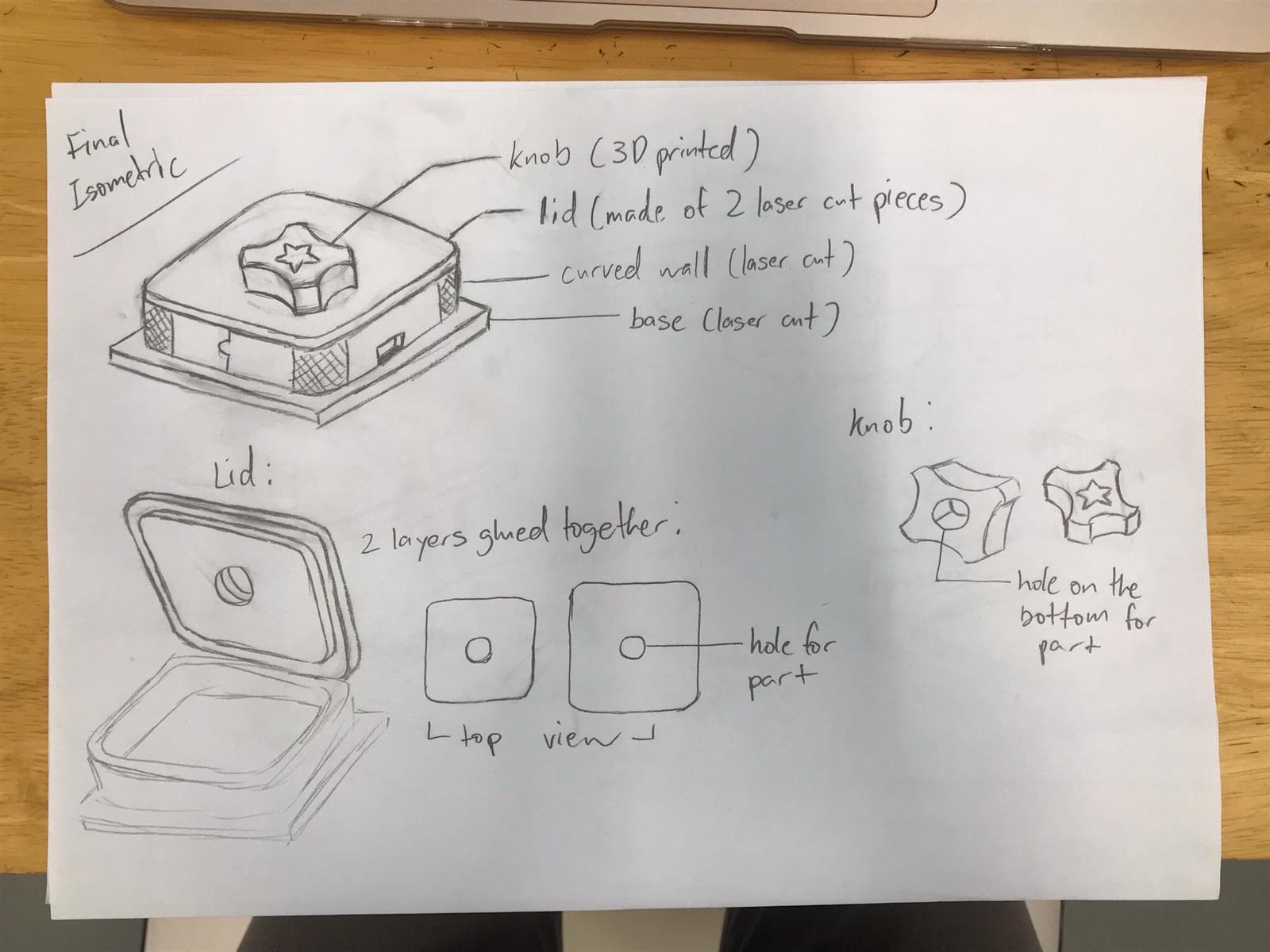
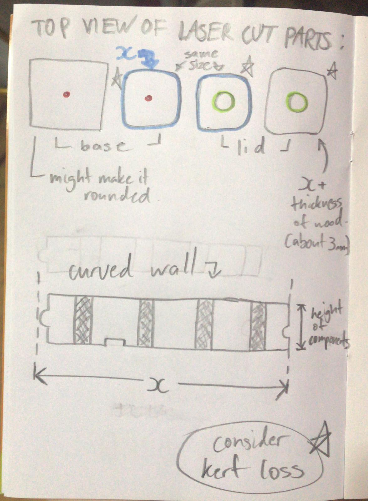
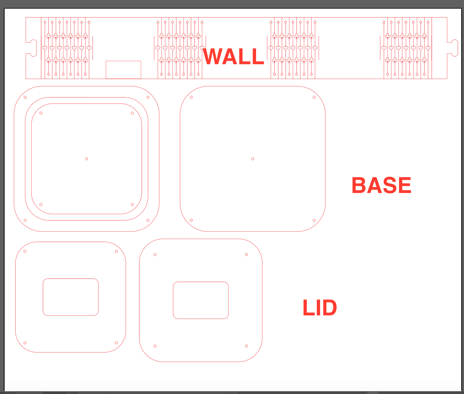
Pieces to laser cut:
Instead of using the b10k rotary potentiometer provided in the kit, I will be using a rotary encoder kindly provided by my lecturer, as it has more
capabilities such as the push button switch that will allow me to make the controller pause and play the music when the button is pressed.
For the wood, there are a few different thickness available in the lab: 2.5mm, 3mm, 4mm, and 5mm. I will be using 2.5mm so that the curve will
have a lower risk of breaking, but this is subject to change based on the testing and result of the flexture curve design.
Bill of Materials Final
- 1 x Rotary encoder (check),
- 1 x Arduino Pro Micro/Arduino Leonardo
- Plywood (2.5mm)
- Filament for 3D printer
Flexture Design
For the flexible laser cut part, I will be using the design from this website (lasercut flexible bracelet) as reference and modifying it to my liking.
Plain design referenceThis is my first attempt at the flexture design, with reference to online designs:
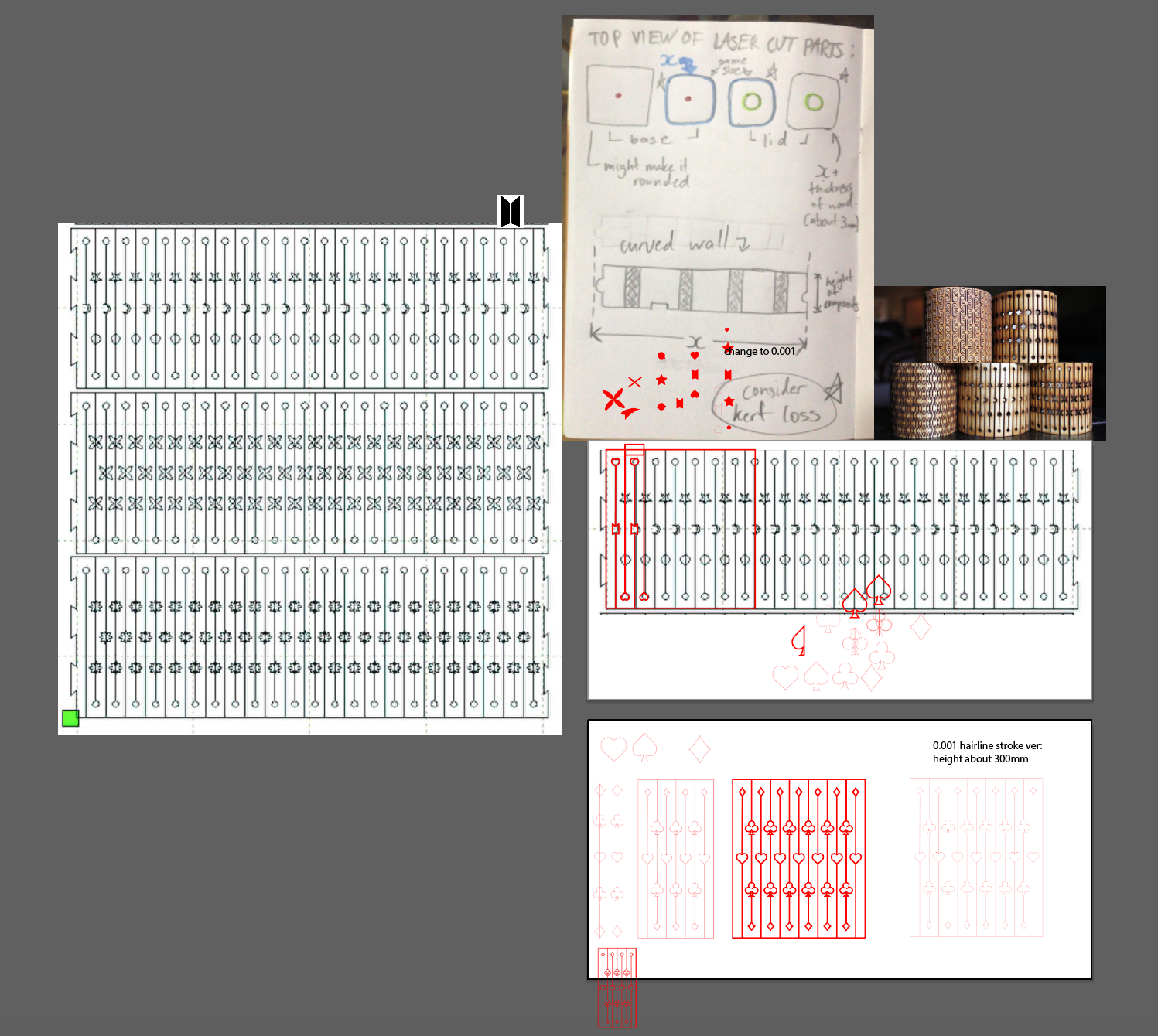
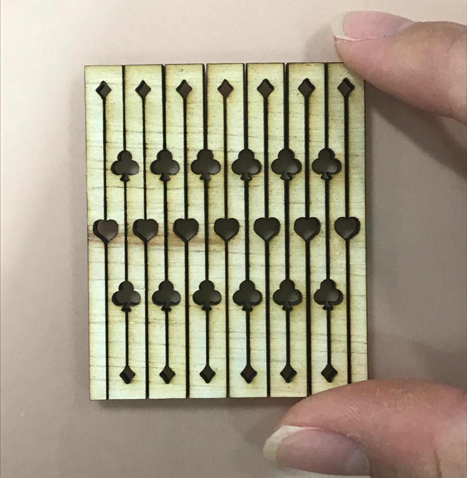
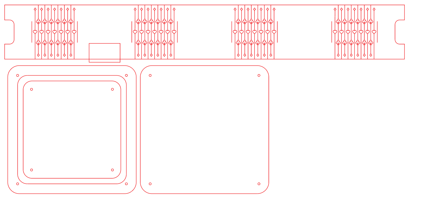
For my second attempt, I used card icons as the theme instead and made sure to line them up so that the smaller icon (diamond) was at the top, preventing it from breakage.
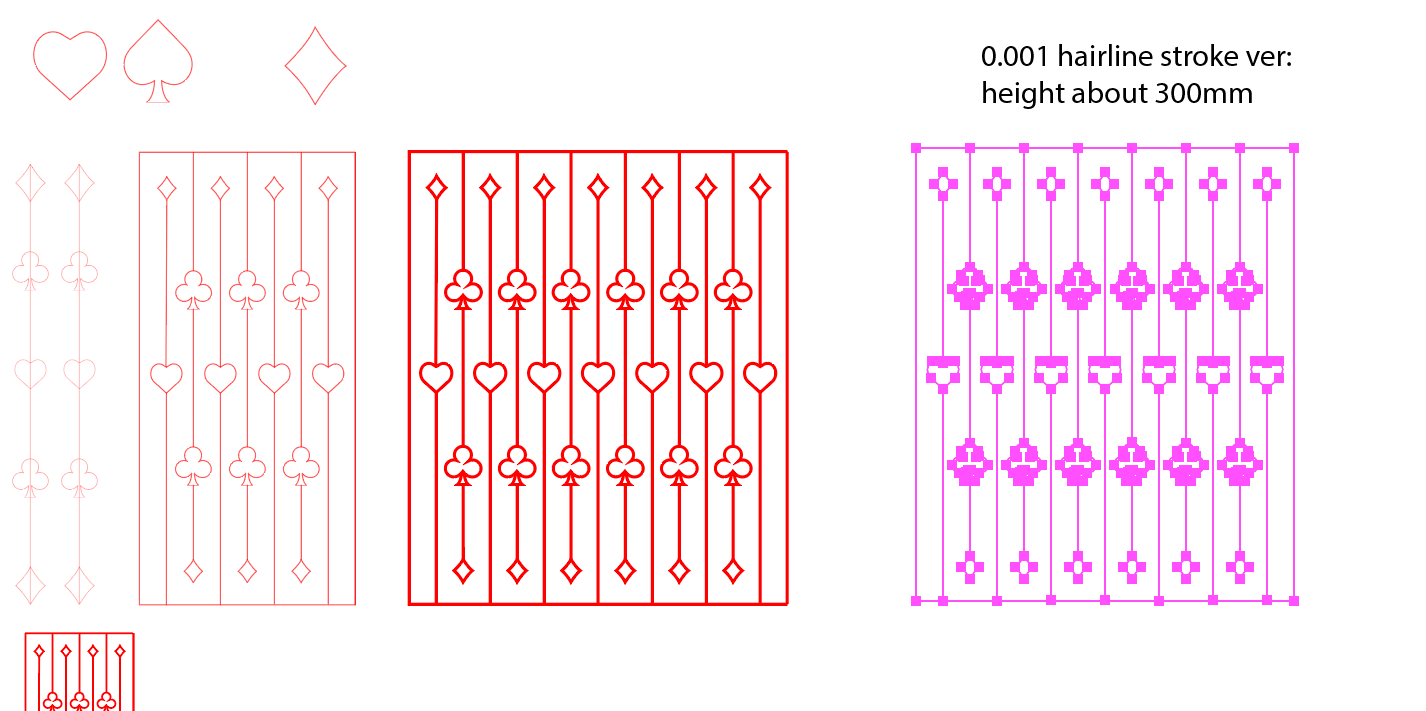
(I used a hairline stroke of 0.001mm in illustrator, but changed it to a thicker stroke for journalling purposes).
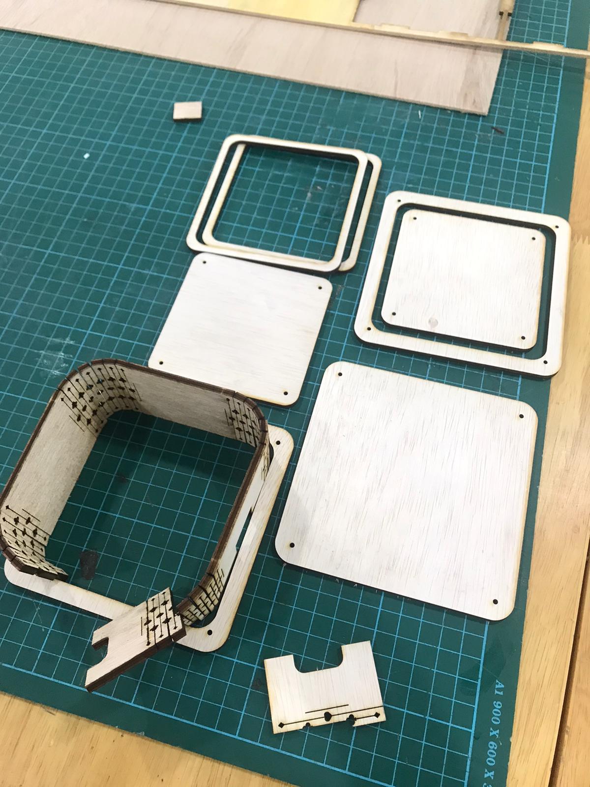
I did a test cut of the curved walls portion I designed, using thicker 3.3mm wood and a height of 50mm.
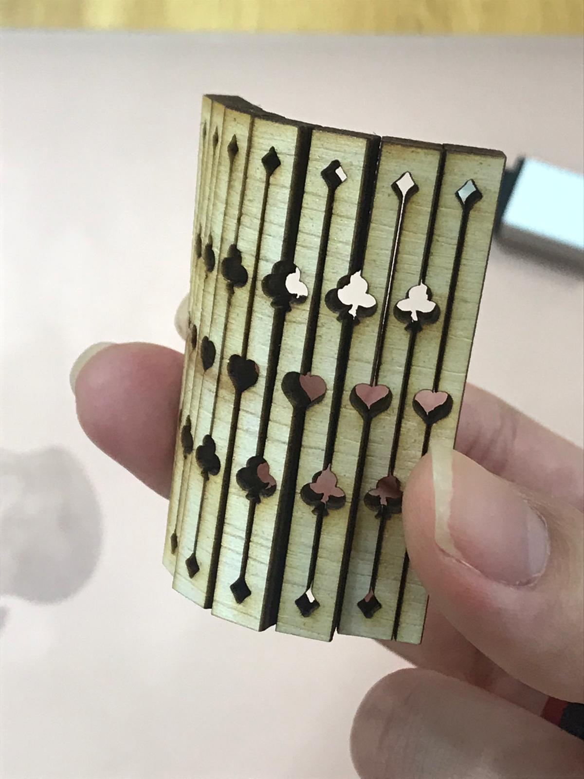
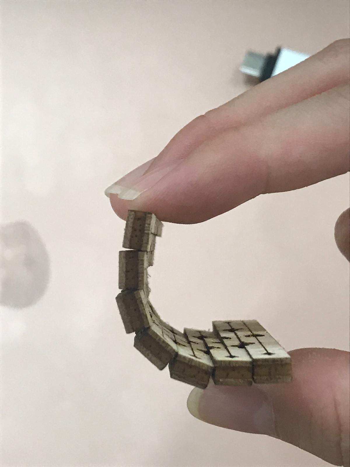
It worked! The piece was able to bend. Thus, I went on to make the other parts, using 50mm as the height. As the box needed to fit the arduino, I thought 100mmx100mm was a good size for it. Therefore, the side of one wall would be 100mm, including 2 curved parts of the wall which were 25mm each after measuring. Hence, the uncut wood part for each side would be 50mm. I adapted the design to the long piece for the wall, removing the line at the ends and using a short line to mark where it ends.
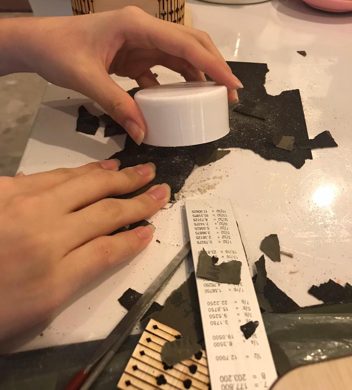
Calculations based on measurements from test cut: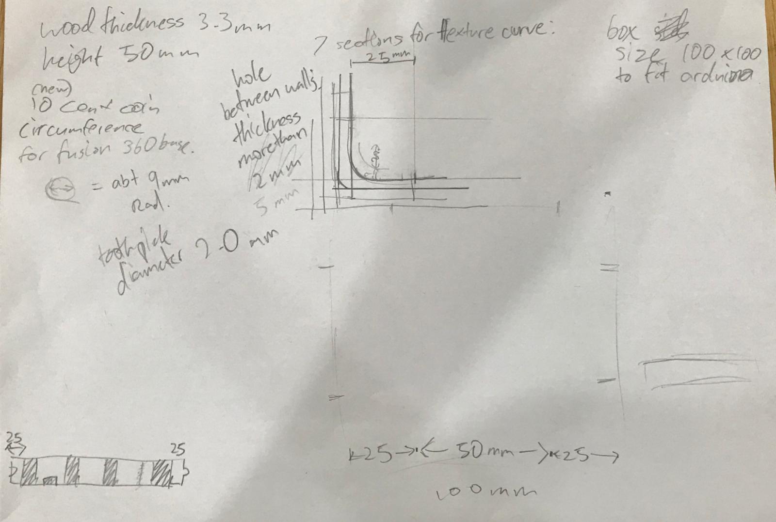
Based on these measurements, I was able to start drawing out the base accurately. I added holes with 2mm diameter to fit toothpicks to align the pieces to stick together.
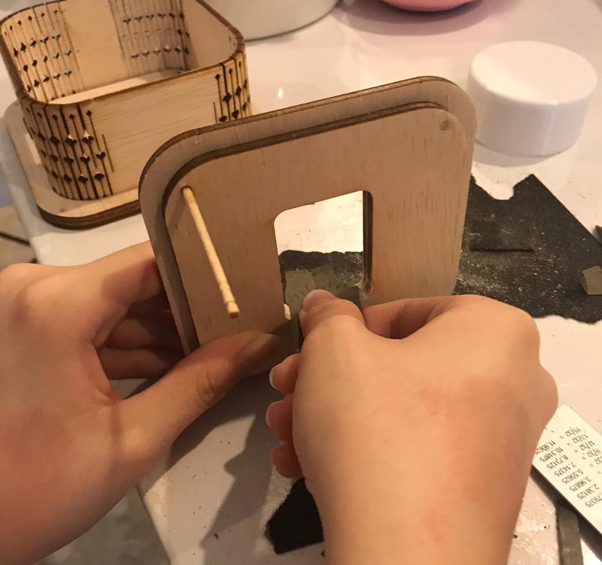
With this design, I lasercut and tried it out.
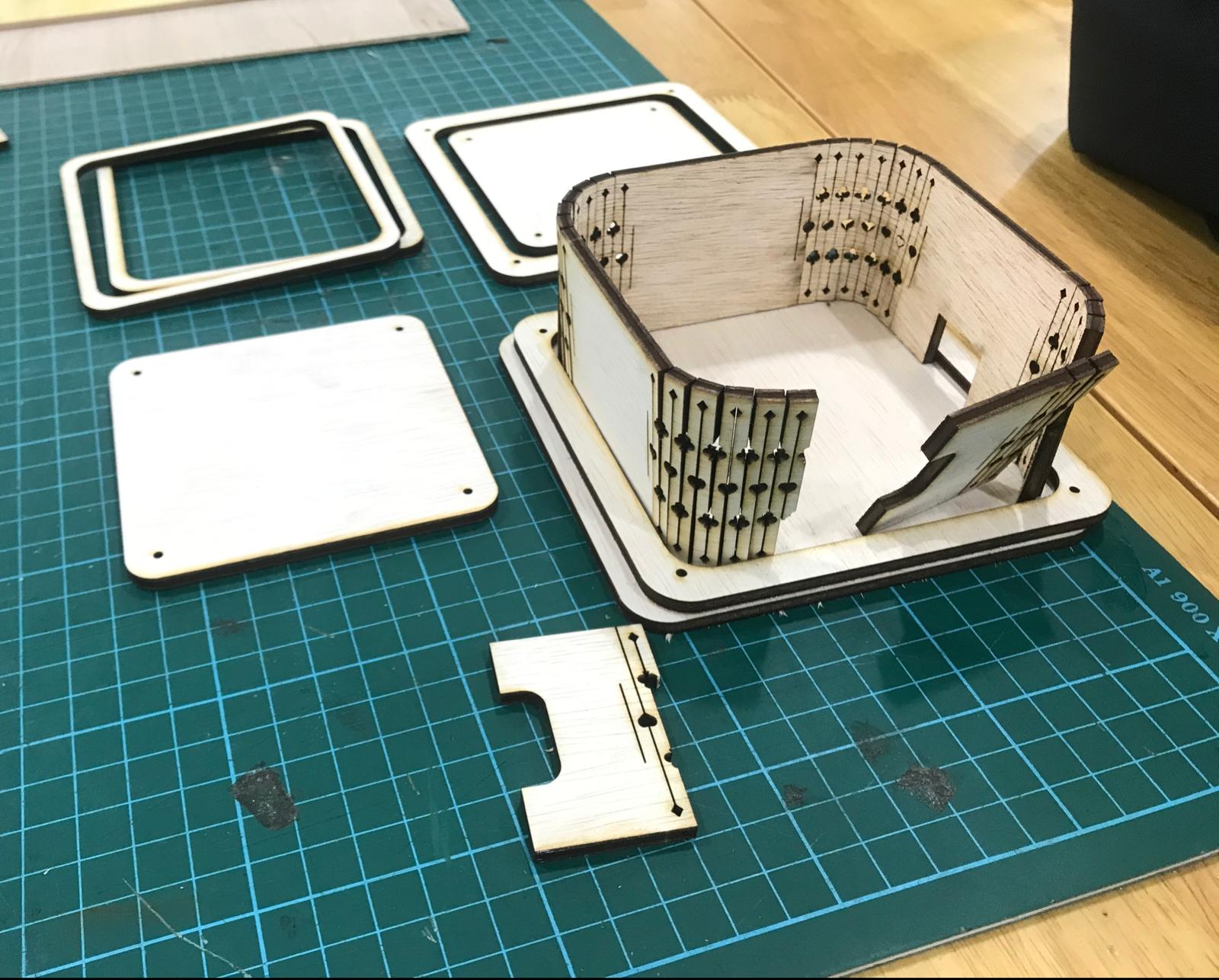
Next, I proceeded to draw out the lid, after measuring the rotary encoder, since it fit. I also changed the design of the lock and made the curved side rounder for future use.
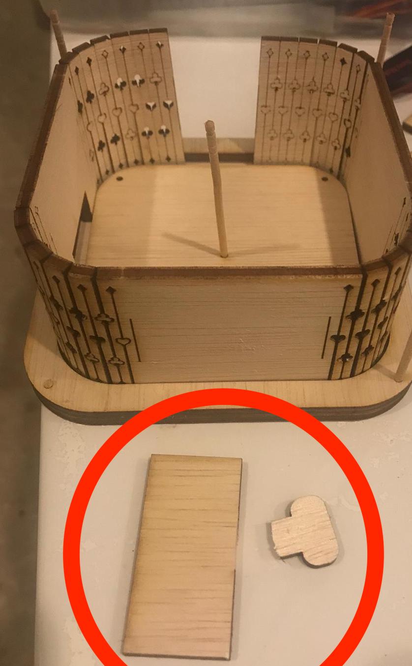
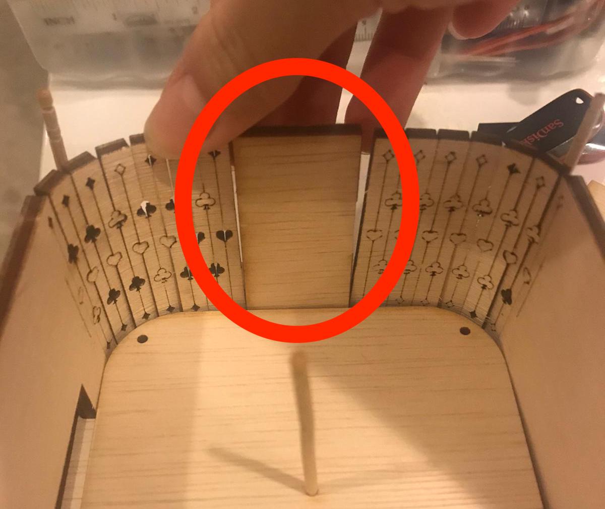
Since I made a mistake with the cutting, instead of wasting wood and recutting the whole piece, I trimmed off a portion to get a rectangular piece of wood which fit in between the gap in the wall and glued it there. I also used toothpicks to align the wood pieces and glued them together. Next, I trimmed the excess off the toothpicks and sanded them down. I lasercut the lid and did the same. With that, my case was completed.
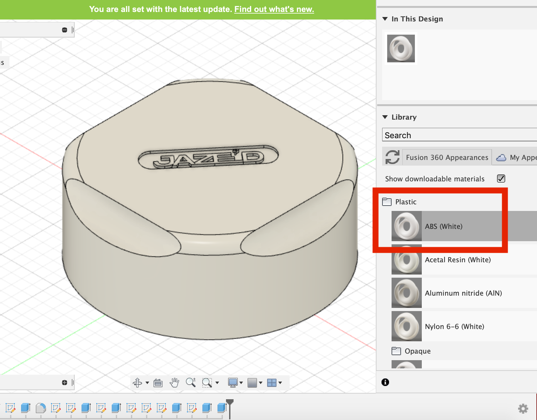
For the volume control knob, I designed one according to my original design, on Fusion 360, with a logo on the top.
- Creating a sketch, I drew out a circle of 100mm (subject to change) and extruded it.
- After extruding up, I created a smaller circle on the bottom to create a hollow using extrude again.
- I used fillet to round the top edge.
- Creating a sketch on each side, I made a wide oval and rotated it at an angle, placing it at the corner of each side.
- Next, I used extrude to cut the finger grooves and repeated that for each side.
- Lastly, I imported my logo from my AI file and placed it on the top, using extrude in the negative space to make it sunken in.
I used ABS WHITE plastic so it would look close to the real version after printing.
After showing it to my lecturer, I made the following changes:
- I will be printing it upside down so that no support will be needed to hold it up.
- I removed the logo on the top and the finger grooves to simplify it.
- The width of the knob would be changed to about 2mm so it would take less time to print.
- I will add a hollow pillar on the inside to allow it to hold and turn the rotary encoder, with a base wrapping around at the top to secure it.
I measured the rotary encoder so that I could figure out how big the button should be and dimensions for the holder of the rotary encoder, as well as the size of the hole for the lid.
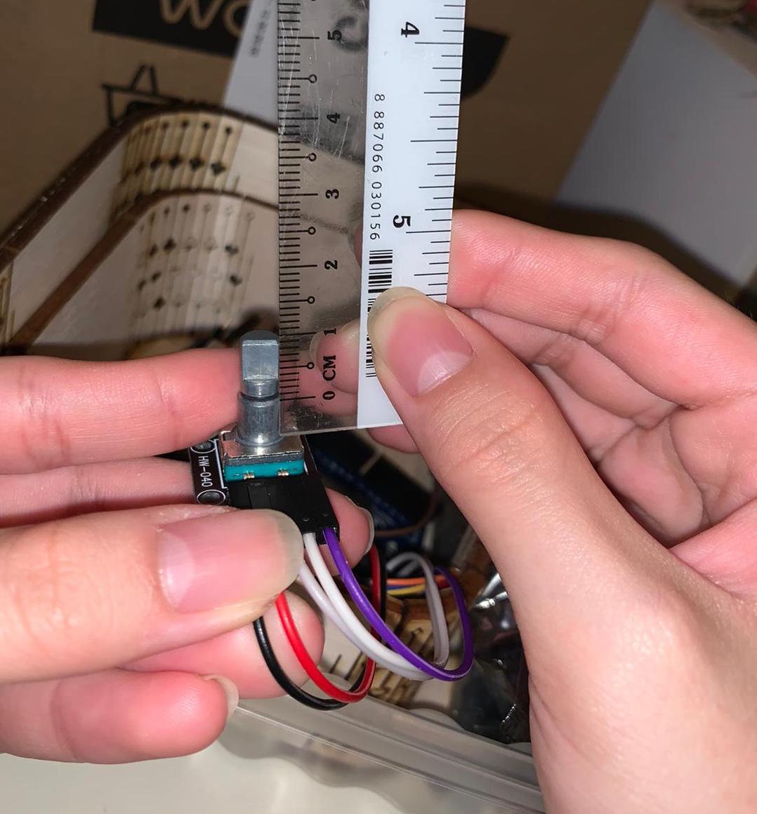
These are the dimensions:
Button - Diameter 6mm, Height 10 mm. Base (bottom half under push button part) height 15 mm. Length 21-40 mm (including allowance for the wire sticking out at the side). From the top 6mm sunken in.
- I changed the dimensions of the entire knob, fitting it to a smaller size that would accomodate the rotary encoder.
- After changing the size, I fixed the rest of the parts that got messed up usign Design History.
- I removed the logo and the finger grooves to simplify it.
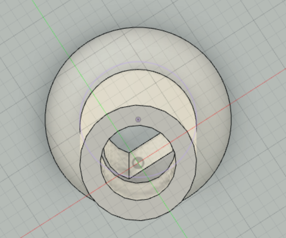
- Using a new sketch, I extruded a hollow pillar that reached all the way to the roof of the knob, adding a cut in the circle to fit the flat side of the rotary encoder.
- I added a base around the pillar to secure it and give it support, by sketching a triangle next to the pillar and using Revolve.
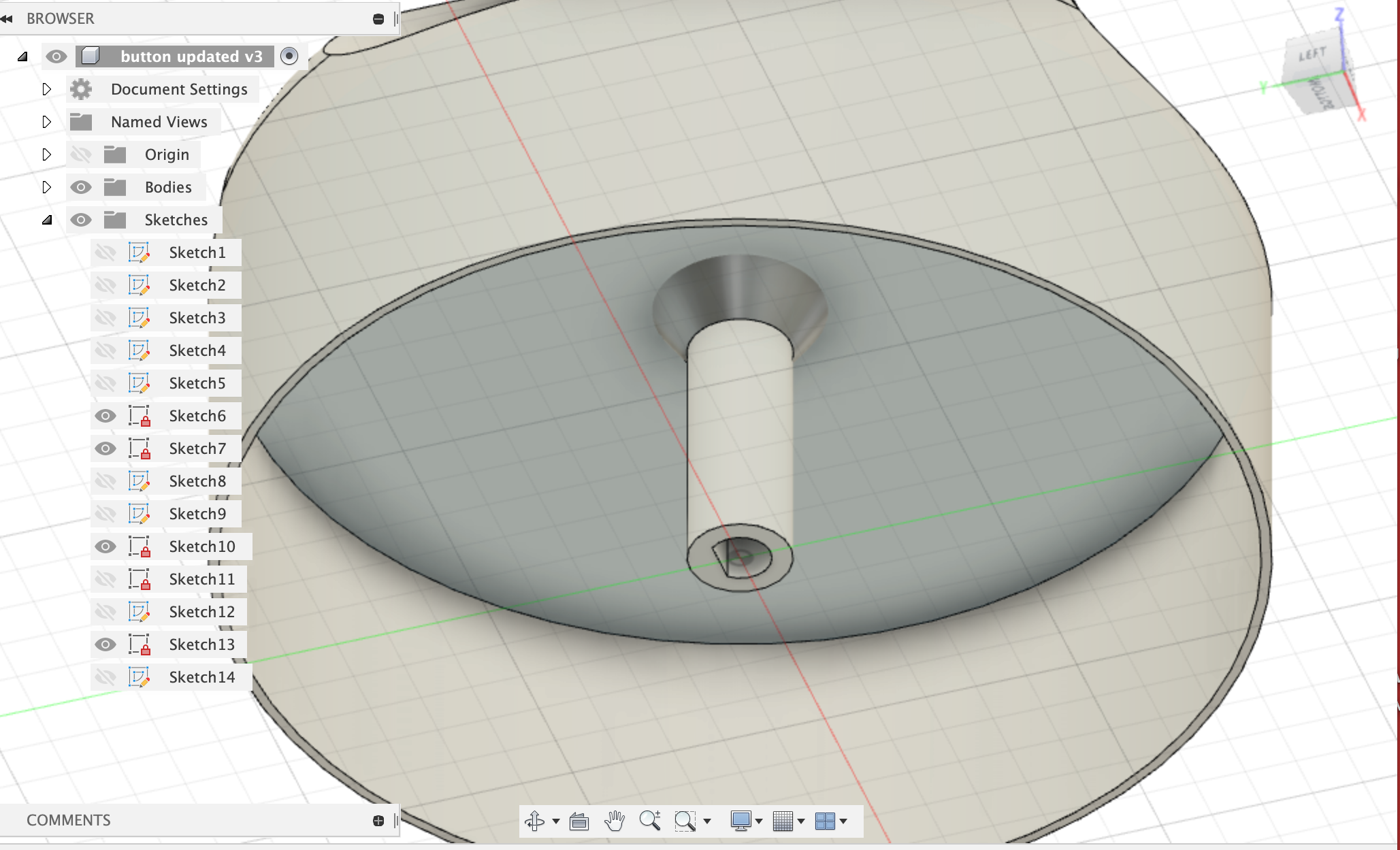
- Lastly, to make it fit the rotary encoder, I used extrude to remove 10mm of the triangular part as well as 0.5mm to fit the bottom half of the push button part in the rotary encoder which is slightly bigger.
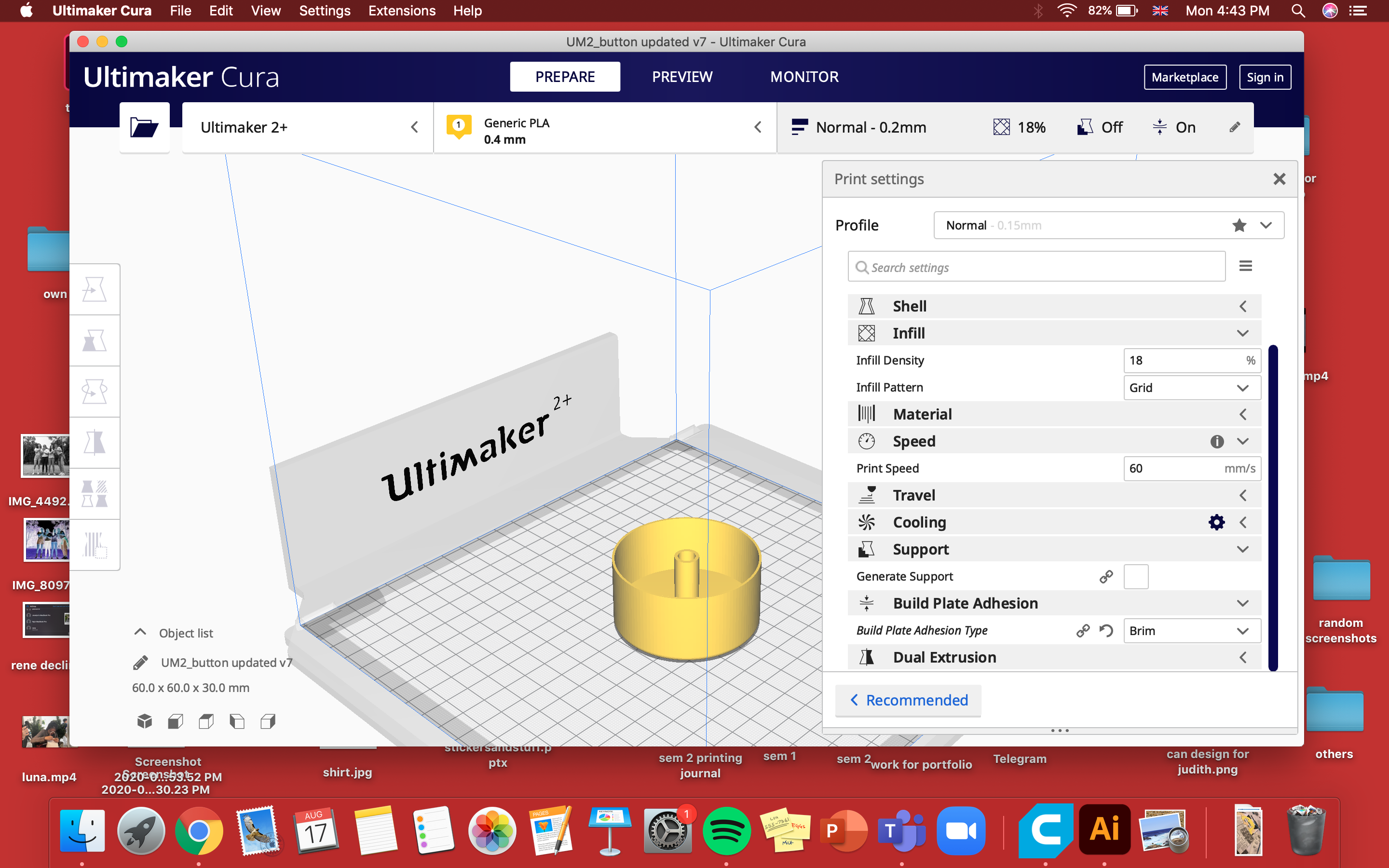
After making the changes, I exported it as an STL file and imported it into CURA to prepare for 3D-printing. I flipped it upside-down so it would not have to generate support.
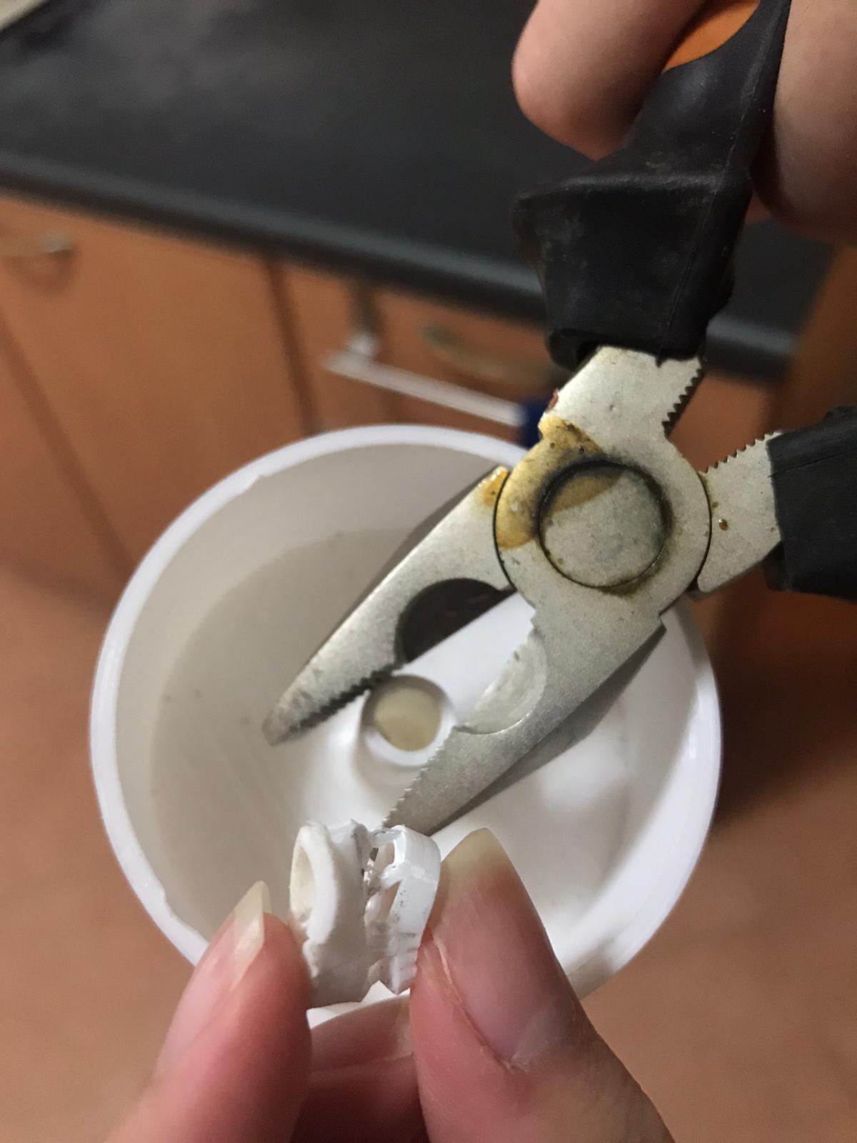
After 3D printing it, I realised that I made some minor mistakes with the calculation of the height of the rotary encoder button. Therefore, the height of the pillar in the cap holding it was wrong. With the help of my muscular dad, I removed a portion of it with pliers and sanded it smooth.
I also sanded the base and the toothpicks in the lid using sandpaper and small files.
Arduino attempts
For the volume control knob programming,
I tried linking up the arduino board to the rotary encoder, and using the codes provided by several websites to programme it.
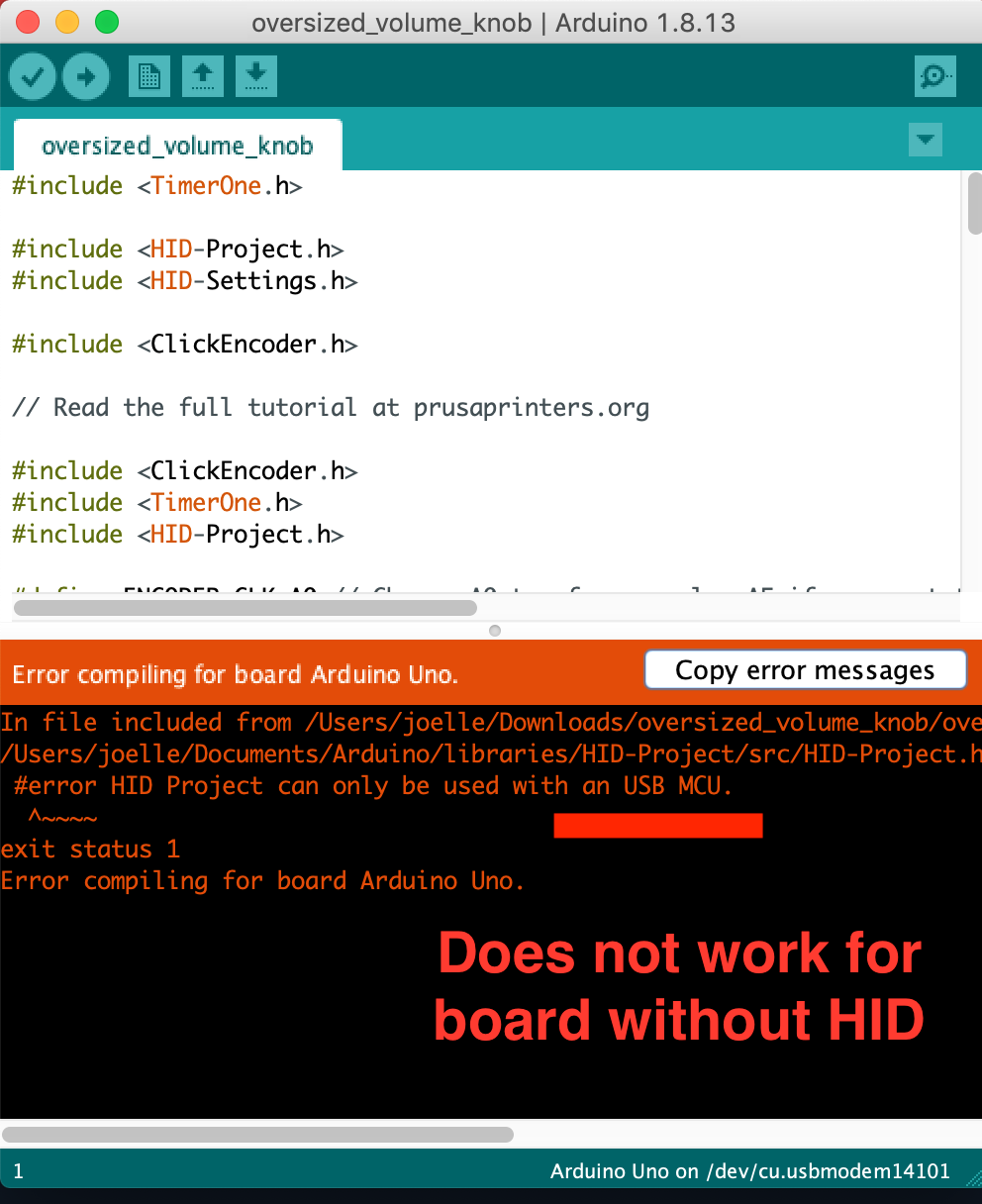
Although I tried different codes from different websites, they didn’t work because I was using the Arduino Uno CDC, while
the boards used in the tutorials online were the Pro Micro and Nano. I received error messages telling me that HID is needed for volume control.
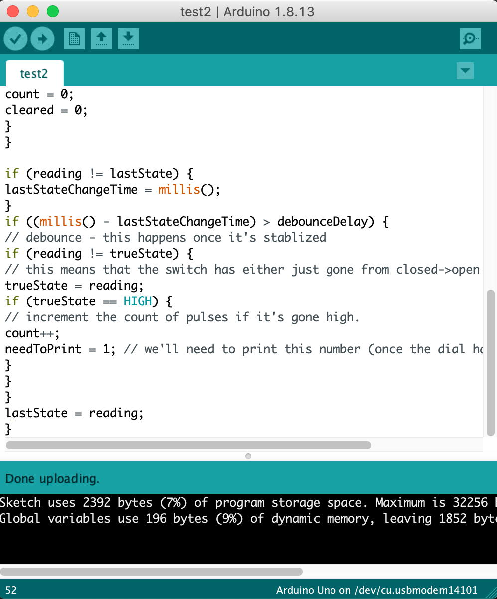
For codes which I successfully uploaded onto the board, no output was given when testing it. I even tried plugging it into a Windows computer, but to no avail.
I also checked with my dad and he confirmed that HID is needed for volume control, saying that I needed to change the board. Thankfully, my lecturer assured me that amongst the two alternatives (Arduino Pro Micro (ATMega32U4) or the Digispark (ATTiny85)), the Digispark was available at FABLAB.
My wiring attempt:
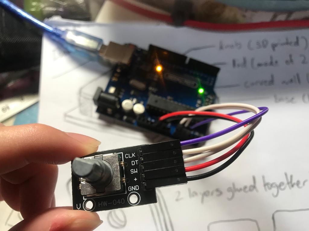
After I received the Digispark from my lecturer, I also obtained some female to female wires to wire the digispark to the rotary encoder. I soldered the Digigspark to the headers
so I would be able to wire it.
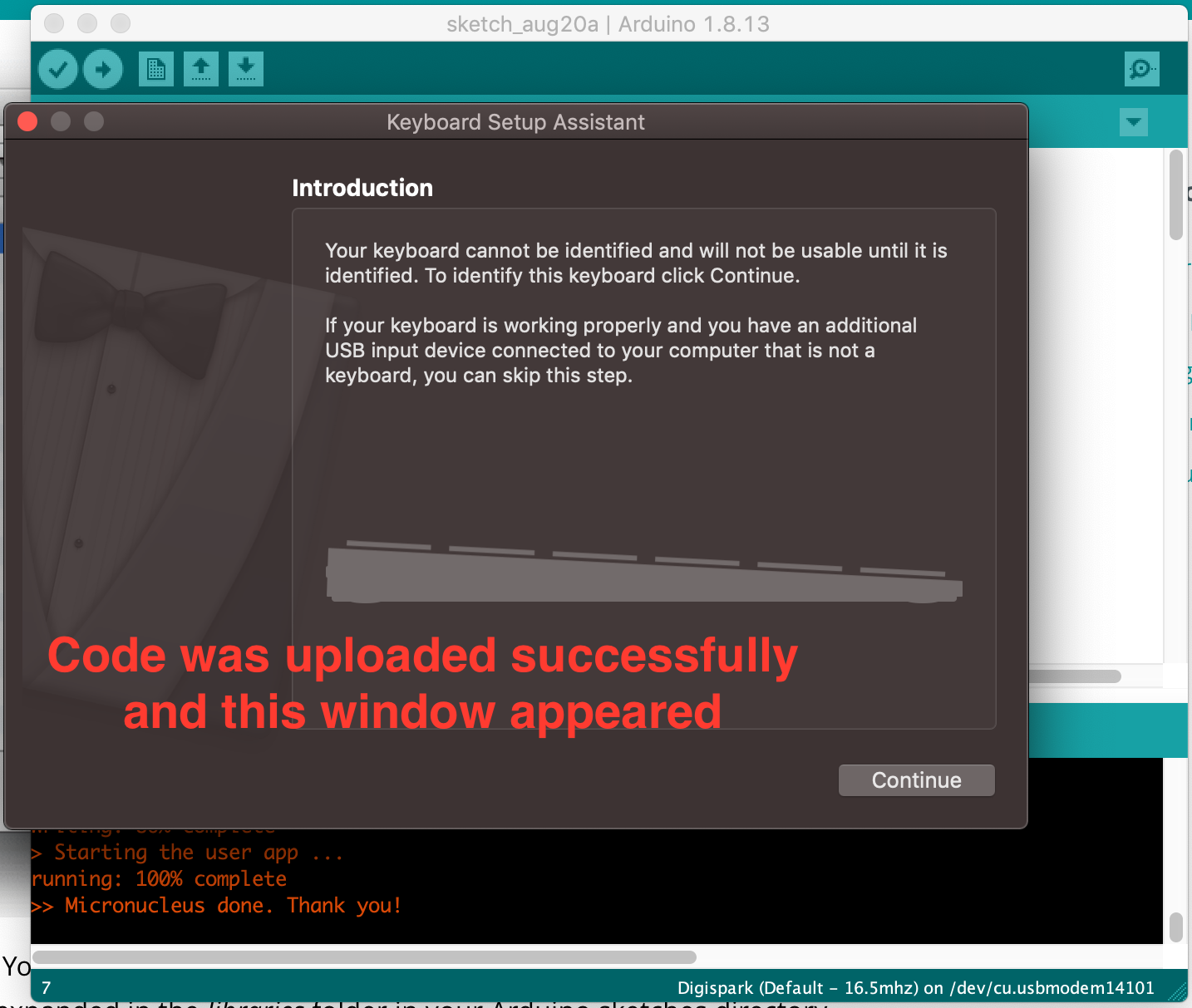
However, I ran into many problems as my computer is a Mac. I faced problems with the Arduino program drivers, codes and others elements. I downloaded and tested many different codes from different websites and got close a few times but was unable to show the output of the volume control when turning the rotary encoder. I also tried downloading the all the programs, codes and libraries on my father’s Windows computer, to no avail. I finally succeeded with one website after many attempts. The volume of the sound could change after turning the rotary encoder on my Mac.
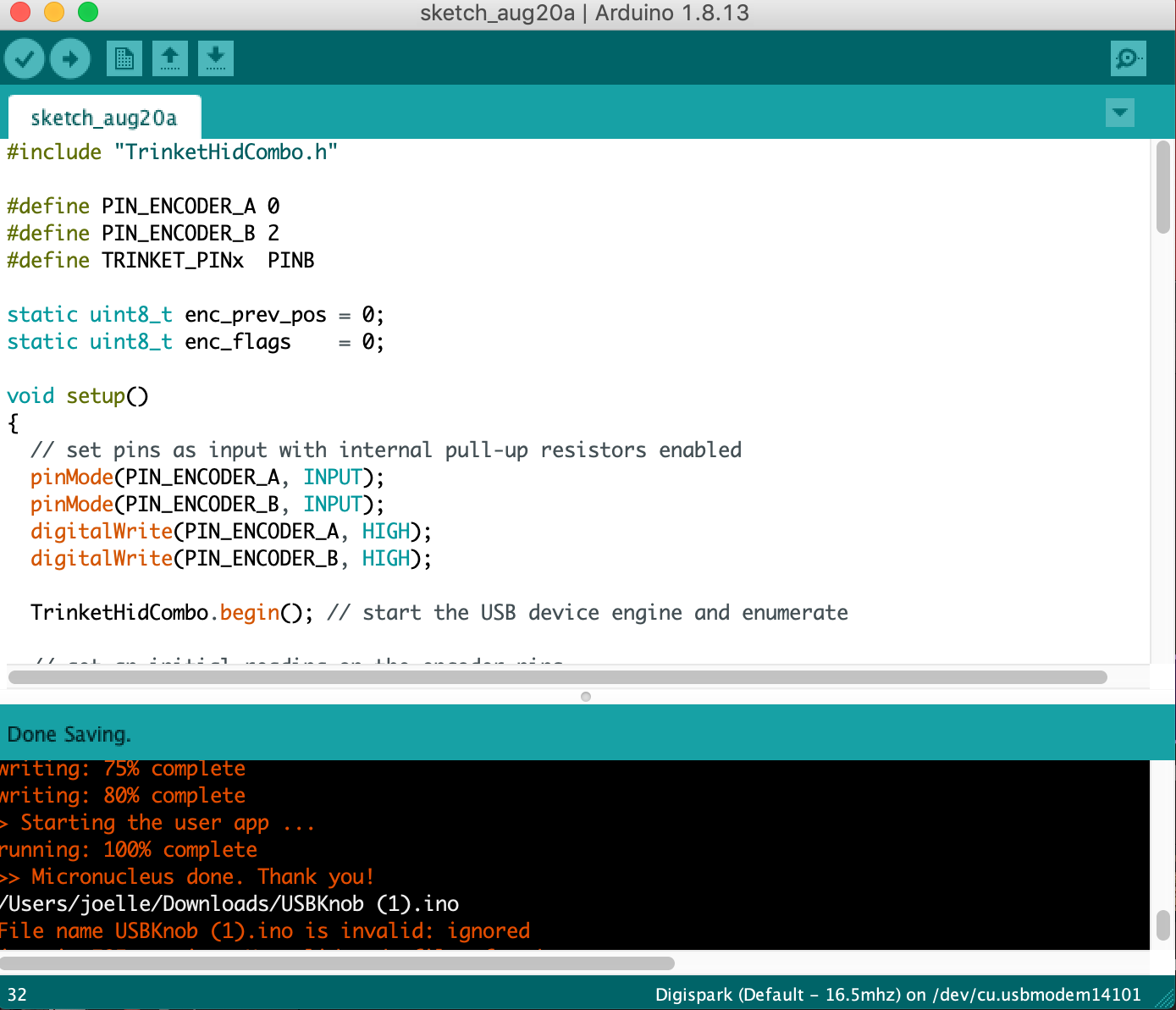
Final how-to on setting up: (the code that worked for me)
- Open the Arduino program and download the Digispark libraries under Manage Libraries.
- Download the 2 codes and files and open them.
- Download the zip file containing TrinketHIDCombo from Adafruit's GitHub site.
- Link the Settings.h file by importing the file and selecting the file location.
- Make sure to select Digispark as the board under Tools.
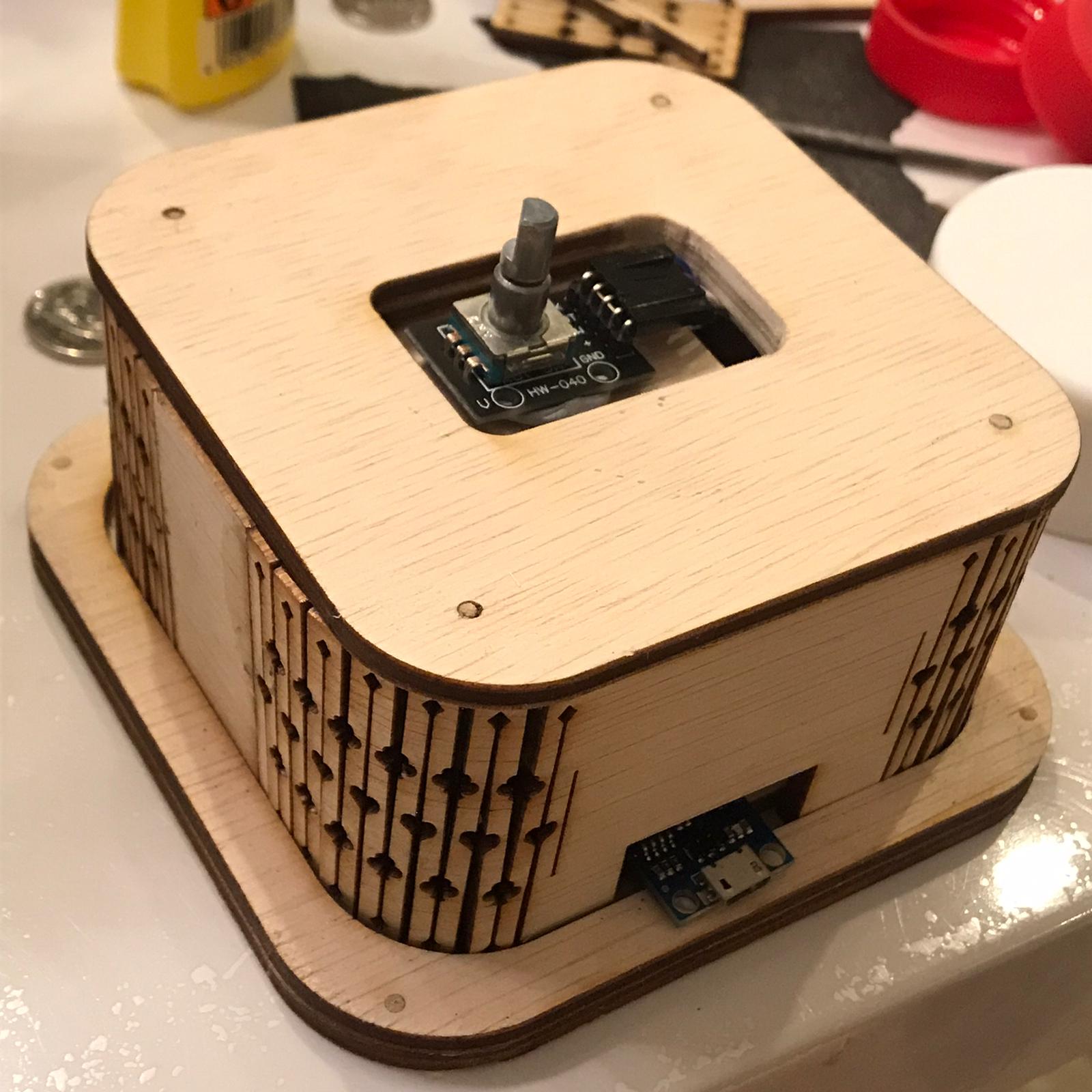
Final Assembly
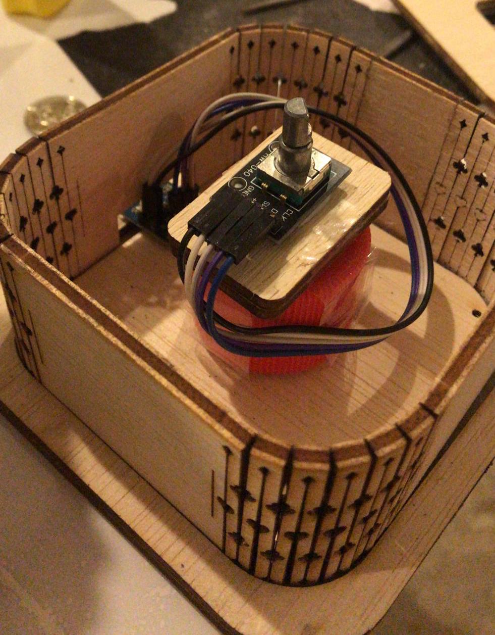
After all the parts were done, I made a makeshift stand out of bottle caps and the leftover wood pieces to elevate the rotary encoder to the opening of the lid. I used masking tape to secure it better, and blue tac to hold it in place. The reason why I did this and did not glue the parts together is so that it will be easy to take apart to return the parts to the school after the project is over, without ruining the box made with the flexture cut design.
Final Video Demo
